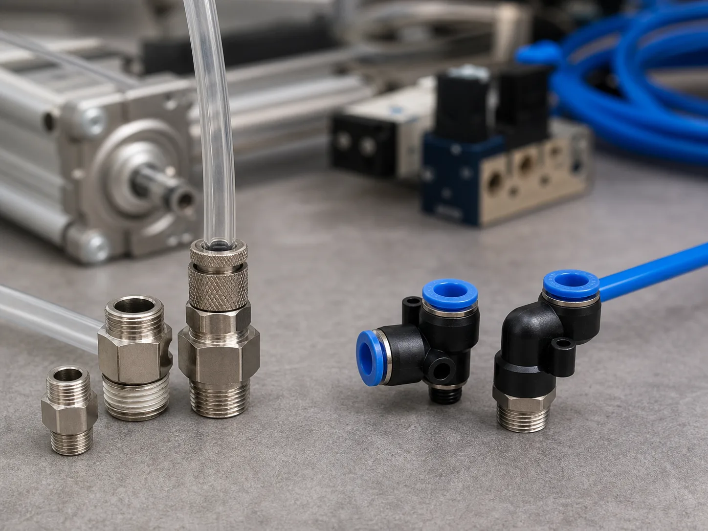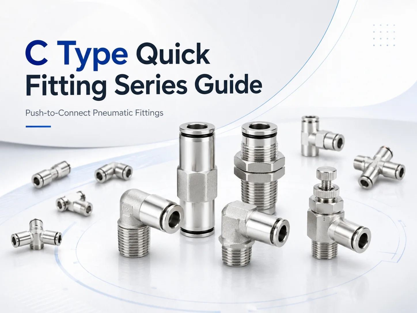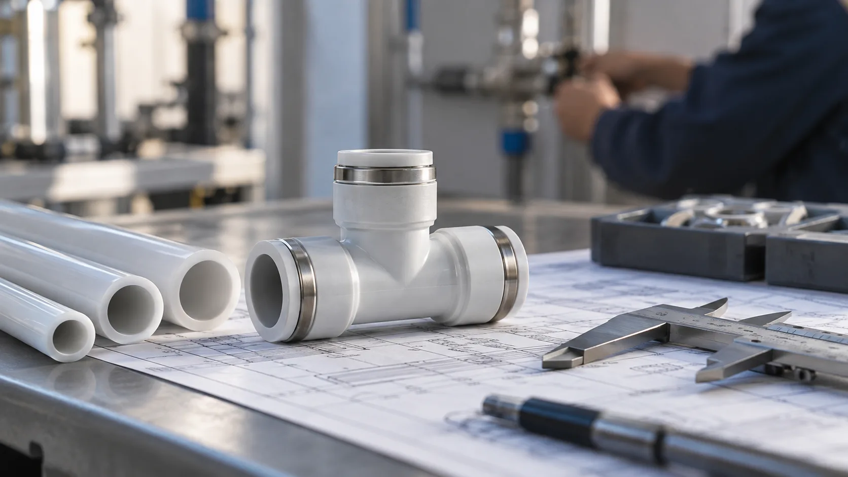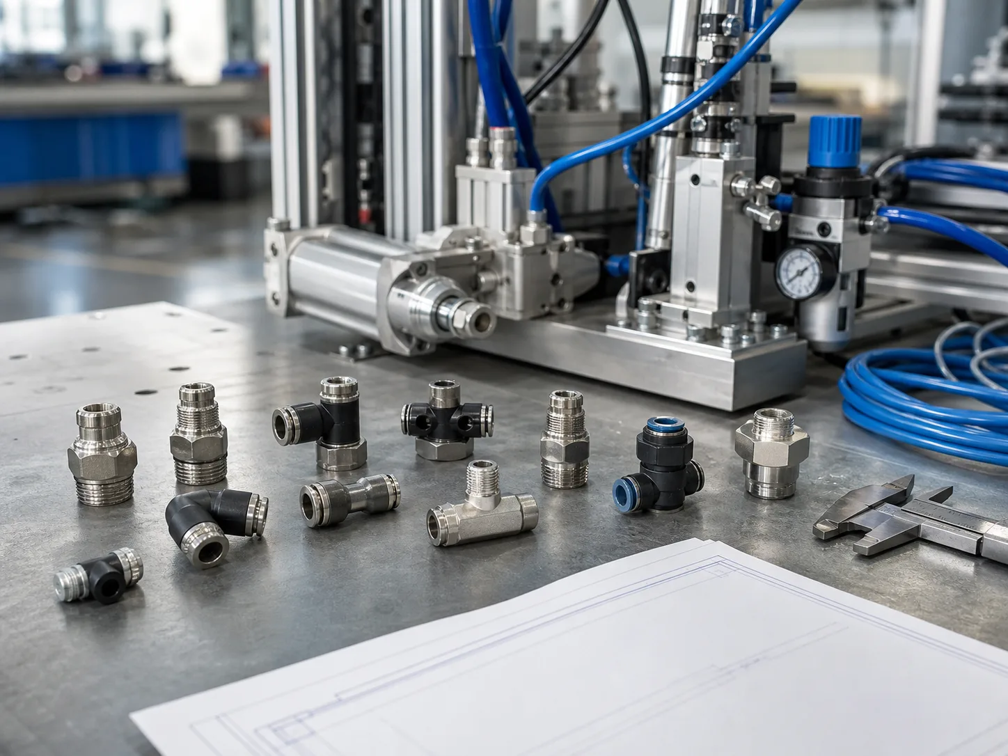
Selecting a pneumatic fitting begins with the route that compressed air must follow. Tube size and thread matter, but the wrong connector shape can still create sharp tube bends, obstruct nearby components, complicate panel access, or add unnecessary joints. A useful layout therefore starts by identifying what each connection must do: enter a port, extend a tube, turn a corner, split a supply, change tube size, cross a panel, isolate a line, or regulate exhaust flow.
This guide compares the main fitting shapes available in the HOMIPNEU pneumatic fittings range. It focuses on machine layout and service access rather than treating every connector as an interchangeable air fitting.
Start with the Connection Task
| Layout Task | Typical Shape | Representative Model | Main Check |
|---|---|---|---|
| Connect tube to an equipment port | Male straight | PC | Tube OD, thread and installation height |
| Extend a tube run | Straight union | PU | Equal tube outside diameter |
| Change tube size inline | Straight reducer | PG | Both tube sizes and downstream flow |
| Turn from a threaded port | Male elbow | PL | Port clearance and tube direction |
| Clear an obstruction | Extended male elbow | PLL | Required reach and wrench access |
| Split one line into two branches | Equal tee or Y | PE / PY | Branch angle, flow and service space |
| Branch while reducing tube size | Reducing tee | PEG | Which port uses the reduced size |
| Create a shared four-line junction | Cross | PZA | Total simultaneous airflow |
| Pass a tube through a panel | Bulkhead union | PM | Panel hole, thickness and nut clearance |
| Turn immediately after a panel | Bulkhead elbow | PLM | Panel geometry and elbow orientation |
| Adjust actuator exhaust flow | Elbow speed controller | SL | Flow direction and adjustment access |
| Isolate a local air line | Hand shut-off valve | HVSF | Valve function and safe maintenance procedure |
Straight Port Connections
PC Male Straight Fitting
A male straight fitting is the direct choice when tube should leave a female threaded port without changing direction. The PC male thread straight fitting combines a push-to-connect tube side with M5 or R-thread options on the equipment side. Its page lists PU and nylon tube compatibility, nickel-plated brass, a stainless steel lock claw, and a 0 to 1.0 MPa working range.
Use this shape only when there is enough axial space to insert and remove the tube. A straight fitting may be physically shorter than an elbow, but it can require more free space in front of the port. Check the full fitting height plus tube bend radius rather than body length alone.
PU Straight Union
The PU straight union fitting connects two equal-size tubes. It is useful for extending a line, dividing a machine into removable modules, or replacing a damaged section after both tube ends have been cut square.
A union should not be used to compensate for misalignment. If two tube runs meet at an angle, select an elbow or reroute the tubing so the joint is not continuously side-loaded.
PG Straight Reducer
The PG straight reducer joins tubes with different outside diameters without changing direction. Published combinations include transitions such as 6-to-4, 8-to-6, 10-to-8 and 12-to-10 mm, with additional size combinations shown on the product page.
Select both diameters and check whether the smaller tube can deliver the required air volume. A reducer solves a mechanical size transition; it does not remove the pressure drop caused by a long or undersized downstream tube.
Elbows for Direction and Clearance
PL Standard Male Elbow
The PL male 90-degree elbow fitting turns tube routing immediately after a female threaded port. It is appropriate beside cylinders, valves, regulators, and manifolds where a straight connector would force a tight tube bend or project into an access area.
Confirm the installed orientation and wrench clearance. The tube should leave the fitting without rubbing a sharp frame edge or blocking adjustment screws, electrical connectors, or neighboring ports.
PLL Extended Male Elbow
The PLL extended male elbow adds reach between the threaded port and the 90-degree tube connection. It can clear a recessed manifold port, thick casting, valve coil, or adjacent fitting.
Do not select the extended version simply because it appears easier to reach. Compare the dimensional drawing with the actual obstruction. Extra height can create a new collision or increase leverage on the threaded connection if tubing is pulled sideways.
Choosing between Tee, Y and Reducing Tee Shapes
PE Equal Tee
The PE T-type fitting creates a compact three-port junction with a 90-degree branch. It works well when tube routes follow rectangular machine frames or when a branch must leave a straight main line at a right angle.
PY Y-Type Tee
The PY Y-type fitting also connects three tubes, but its body geometry directs the branches differently. Select PE or PY from the real tube paths, not from an assumption that one shape always produces better flow. Downstream tube length, valve capacity and actuator demand have more influence on branch performance than the letter in the model name.
PEG Reducing Tee
The PEG reducing tee combines branching and tube-size conversion in one component. It can reduce the number of joints where a smaller actuator or pilot line branches from a larger distribution tube.
Mark the intended size at each port on the circuit drawing. For repetitive OEM assembly, record the full model code rather than writing only reducing tee in the bill of materials.
Cross and Multi-Way Distribution
The PZA four-way cross fitting creates a common junction for four tube ports. It can make a compact passive distribution point, while the PK five-way fitting provides another option when more branches must share one supply.
More ports do not automatically make a better layout. If individual branches require isolation, pressure regulation, metering, identification, or diagnostic access, use a suitable manifold or separate controlled branches. Calculate the total simultaneous flow before concentrating several consumers at one fitting.
Bulkhead Fittings for Panels and Enclosures
PM Straight Bulkhead Union
The PM bulkhead union supports a tube-to-tube connection through a panel. It separates internal and external routing and prevents a loose tube from simply passing through an unprotected hole.
Selection requires more than tube diameter. Check panel-hole size, maximum panel thickness, nut access, body length, tube insertion clearance, and release-collar access on both sides.
PLM Bulkhead Elbow
The PLM bulkhead elbow is useful when the line must turn at the panel rather than continue straight. It may reduce the depth needed behind an enclosure wall, but the elbow orientation and mounting hardware still need room for installation and service.
When the Connection Must Also Control Air
SL Speed Control Elbow
The SL elbow speed control valve combines a tube-to-thread connection, a 90-degree route and adjustable airflow control. It is selected to influence cylinder or actuator speed, not merely to join tubing.
Confirm the required metering direction and install the controller where the adjustment can be reached without removing guards or disturbing tubing. A speed controller does not replace a pressure regulator, directional valve, safety exhaust valve, or manual isolation valve.
HVSF Hand Shut-Off Valve
The HVSF pneumatic hand valve adds local air shut-off at a threaded connection. An inline alternative such as the PA inline air control valve can be considered where both sides connect to tubing.
Choose the valve configuration from the required flow path and maintenance procedure. A local hand valve is not automatically a lockable energy-isolation device; machine safety requirements must be addressed separately.
Seven Checks before Finalizing the Layout
- Tube outside diameter: push-in fitting sizes refer to tube OD, not tube ID.
- Thread gender and standard: confirm male or female connection, M, R, G, PT, NPT or other specified thread, and the sealing method.
- Published operating limits: check fluid, pressure and temperature on the exact product page. Do not transfer one model’s rating to the entire category.
- Airflow demand: consider tube length, internal passage, valve capacity and simultaneous consumption.
- Assembly space: allow room for a wrench, tube insertion and panel hardware.
- Service access: the release collar, flow adjustment and shut-off handle must remain reachable.
- Tube bend radius: route tubing without sharp bends, rubbing, tension or continuous side load.
For a deeper review of BSPT, NPT, metric and G connections, see the pneumatic fitting thread guide.
Layout Examples
Compact Cylinder Installation
Use a PC fitting when the tube can leave the port straight, a PL when it must turn immediately, and a PLL when the port is recessed. Select an SL only when adjustable flow is part of the circuit requirement.
Control Cabinet Boundary
Use a PM when tubing should pass straight through the panel and a PLM where a 90-degree turn improves internal clearance. Keep the bulkhead nut and release collars accessible from the intended service side.
Main Line with Smaller Branches
Use PE or PY for same-size branching and PEG when the branch tube must be smaller. A PG can create an inline transition before or after the branch if that arrangement is clearer and easier to stock.
Serviceable Machine Module
Use PU unions at deliberate module boundaries and a suitable hand valve where local shut-off is required. Do not scatter unions through the circuit merely to correct poor tube measurement.
Common Selection Errors
- Choosing a fitting by photograph without checking dimensions.
- Confusing tube outside diameter with nominal hose size.
- Mixing thread standards that appear similar.
- Using a straight connector where the tube cannot maintain its bend radius.
- Using an equal tee when the branch needs a different tube size.
- Concentrating too many consumers at one cross or five-way connector.
- Mounting a bulkhead fitting without checking panel thickness.
- Hiding a release collar or speed adjustment behind another component.
- Assuming every product in the category has the same fluid or pressure rating.
FAQ
Which fitting should connect a tube directly to a threaded port?
Use a straight PC when the tube can leave axially, or an elbow such as PL when the route must turn 90 degrees. Confirm tube OD, thread and clearance.
What is the difference between PE and PEG?
PE is an equal-size T fitting. PEG is a reducing tee for different tube sizes. Verify the location of each tube size before ordering.
When is a Y fitting better than a T fitting?
Choose the shape that matches the physical branch directions and service space. Do not assume that the Y shape alone guarantees better circuit performance.
Should a cross fitting replace a manifold?
Only when the circuit needs a passive common junction. Use a manifold when branches require individual control, isolation, regulation, labeling or diagnostics.
Which fitting is used through a panel?
PM is a straight bulkhead union. PLM adds a direction change at the panel. Check panel dimensions and access on both sides.
Build the Layout before Ordering the Fittings
The correct fitting shape follows the job at each connection point. Mark every straight port, extension, reduction, corner, branch, panel crossing and control point on the pneumatic drawing. Then confirm tube OD, thread, operating limits, airflow, dimensions and service access against the exact product page.
For model confirmation, provide the circuit drawing, tube sizes, thread requirements, working conditions and expected quantity when requesting a quotation.