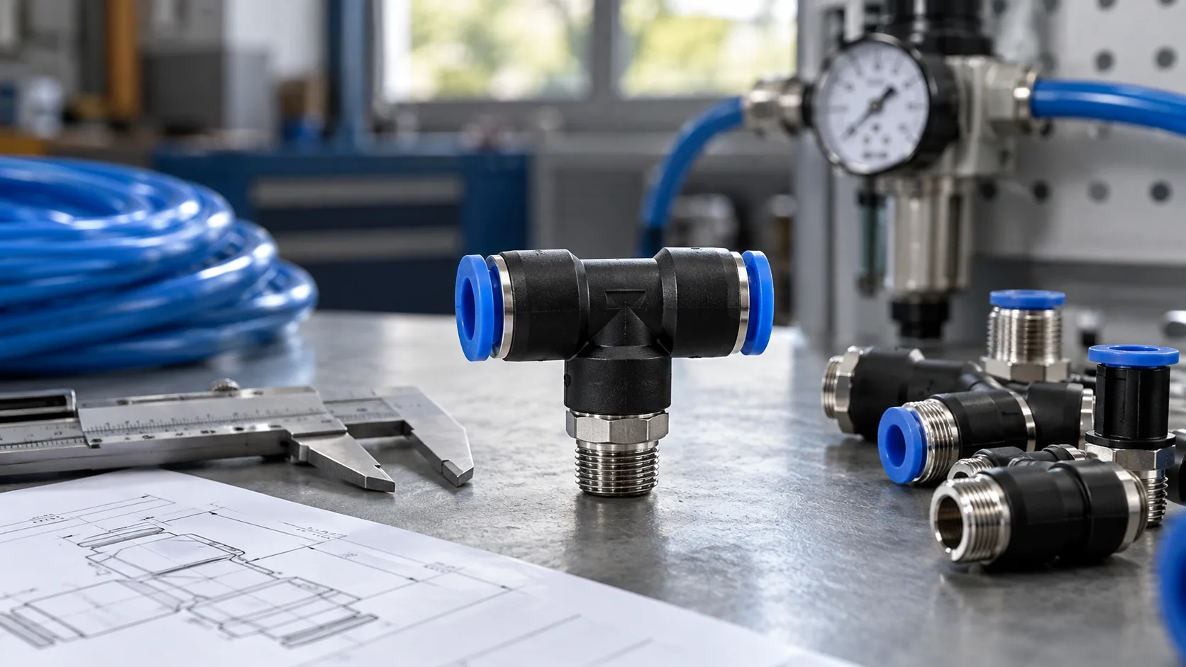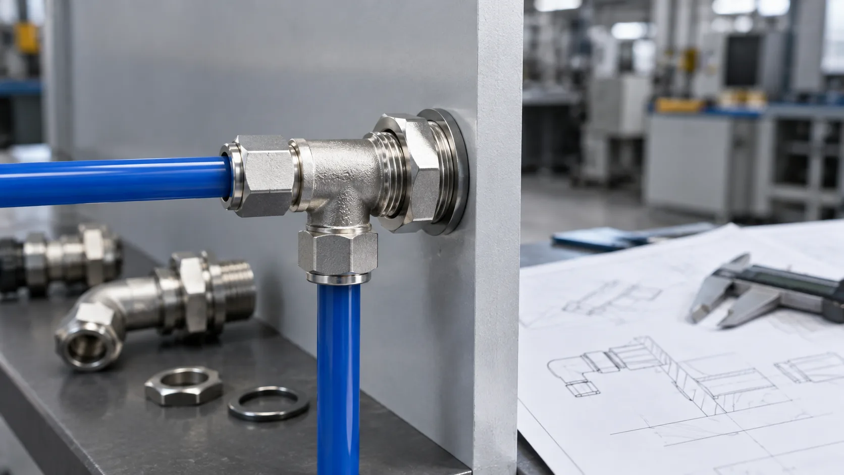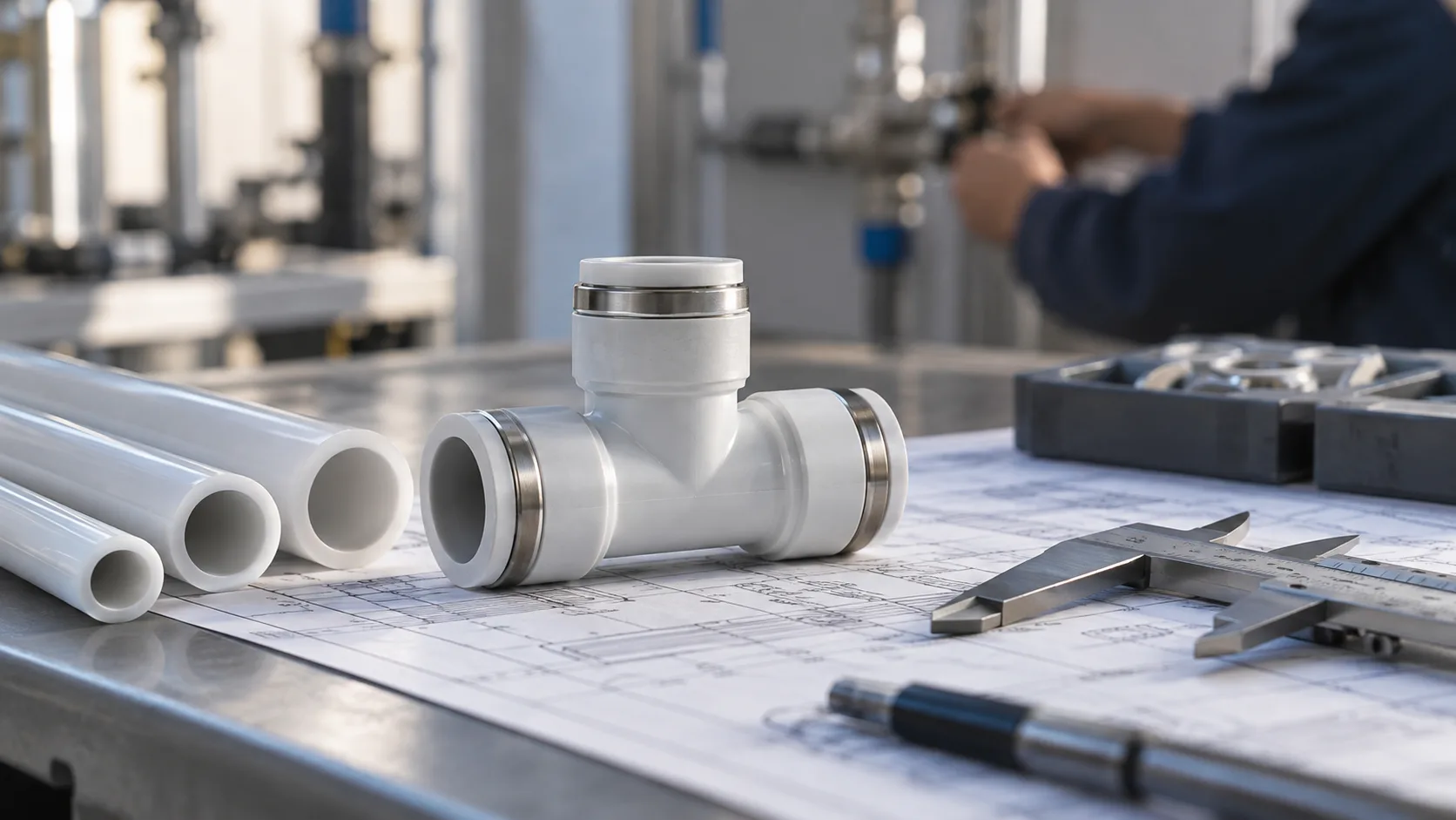
A machine air line often needs to continue in one tube size while supplying a smaller branch to a nearby device. Using an equal tee followed by a separate reducer can work, but it adds connections and takes up space. A pneumatic reducing tee combines the branch connection and tube-size transition in one fitting.
The HOMIPNEU PEG Reducing Tee Pneumatic Fitting is a push-to-connect air connector for this type of mixed-size routing. Its published range includes 11 combinations, from PEG6-4 to PEG16-12, for compatible PU and nylon tubing.
Choosing the correct PEG model starts with the outside diameter of all three tubes. It also requires checking the smaller branch’s airflow demand, the shared supply capacity and the installation space. This guide explains those decisions with a model chart and practical machine-layout examples.
What Is a PEG Pneumatic Reducing Tee?
A PEG fitting joins three pneumatic tubes in a T-shaped connection. In the listed product range, two sockets share one tube size, identified as D1, while the third socket accepts a smaller tube, identified as D2. The product table labels these dimensions D1 × 2 and D2.
For example, PEG8-6 has two connections for 8 mm OD tubing and one connection for 6 mm OD tubing. It does not have three different socket sizes. Confirm the D1 and D2 locations on the product drawing when planning the tube route.
The fitting provides a common air passage between its ports. It does not include a regulator, shut-off mechanism or adjustable flow control. Its purpose is to connect unequal tube diameters while creating an air branch.
Why Use a Reducing Tee in a Compressed-Air Circuit?
Different parts of a machine can need different tube sizes. A local supply route may use larger tubing to serve several devices, while a short connection to a small valve or actuator uses a smaller tube. A PEG fitting can make that transition at the branch point.
Compared with an equal tee connected to a separate reducer by a short tube, an integrated reducing tee uses fewer parts and tube joints. That can make a compact installation easier to assemble and document. It still needs sufficient clearance for full tube insertion and later removal.
The best location is a branch point where the required sizes are already established by the circuit design. Selecting a smaller tube purely to save space can cause unacceptable pressure loss if the downstream device needs more air than the line can deliver.
PEG Fitting Specifications
| Parameter | Published specification |
|---|---|
| Operating fluid | Air |
| Connection type | Three push-to-connect tube sockets |
| Size arrangement | Two D1 connections and one smaller D2 connection |
| Operating pressure range | 0–0.9 MPa, equivalent to 0–9 bar |
| Proof pressure | 1.32 MPa, equivalent to 13.2 bar |
| Ambient and fluid temperature | 0–60°C |
| Compatible tubing | PU tube and nylon tube |
| Tube sizes across the listed range | 4–16 mm outside diameter, in the combinations below |
The proof pressure is a test reference, not the allowable continuous operating pressure. The assembled circuit must remain within the lowest applicable rating of the fitting, tubing and connected equipment.
PEG Reducing Tee Size Chart: All 11 Models
The dimensions below follow the product table. D1 and D2 identify tube outside diameters. B and E are drawing dimensions in millimeters; refer to the product illustration for their locations when checking space.
| Model | D1 tube OD, two ports | D2 tube OD, one port | B | E |
|---|---|---|---|---|
| PEG6-4 | 6 mm | 4 mm | 40 | 19 |
| PEG8-6 | 8 mm | 6 mm | 44 | 21.5 |
| PEG8-4 | 8 mm | 4 mm | 44 | 21 |
| PEG10-8 | 10 mm | 8 mm | 52 | 25 |
| PEG10-6 | 10 mm | 6 mm | 52 | 25 |
| PEG12-10 | 12 mm | 10 mm | 56 | 27.5 |
| PEG12-8 | 12 mm | 8 mm | 56 | 26.5 |
| PEG14-12 | 14 mm | 12 mm | 62 | 30 |
| PEG14-10 | 14 mm | 10 mm | 62 | 30 |
| PEG16-14 | 16 mm | 14 mm | 66 | 32.5 |
| PEG16-12 | 16 mm | 12 mm | 66 | 32 |
The range does not establish every possible size combination between 4 and 16 mm. If the required combination is absent, request confirmation of another model or an approved reducing arrangement.
How to Read PEG8-6 and Similar Model Codes
In the HOMIPNEU table, PEG identifies the reducing tee family. The first number specifies the two D1 tube sockets, and the second number specifies the smaller D2 socket. PEG10-6 therefore means two 10 mm OD connections and one 6 mm OD connection.
These are tube dimensions, not thread sizes. A designation such as PEG8-4 does not mean an 8 mm tube combined with a quarter-inch threaded port. This product connects tubing at all three ports; a connection directly to a threaded valve or cylinder requires a suitable threaded fitting elsewhere in the circuit.
A clear purchase description is “PEG8-6, two 8 mm OD tube ports and one 6 mm OD tube port.” Including the written dimensions helps prevent confusion when ordering across suppliers or replacing an existing connector.
Does a Reducing Tee Reduce Air Pressure?
A reducing tee changes the tube connection size. It does not maintain a lower downstream pressure in the way a pressure regulator does. With the circuit at rest and no isolating device between the connected lines, a smaller branch can still reach the supply pressure.
During flow, the smaller passage and connected tube may cause pressure loss. The amount changes with demand and circuit resistance, so it is not a controlled pressure setting. If a device requires a lower maximum pressure, specify an appropriate regulator and the controls required for that application.
Similarly, a reducing tee does not divide airflow into fixed percentages. Tube bore, length, valves and downstream loads determine how much air travels through each branch.
Choose by Tube OD, Then Check the Bore
Push-to-connect sockets are selected by tube outside diameter. The bore, or inside diameter, affects the available flow area. Both dimensions matter, but they answer different selection questions.
For instance, two compatible tubes can both have a 6 mm outside diameter while using different wall thicknesses and internal bores. Both may match the nominal socket size, yet their pressure ratings and airflow performance may differ.
Use the tubing manufacturer’s specification to confirm tolerance, material and operating conditions. Do not substitute an inch-size tube for a metric one because it appears close in size. The seal and retention mechanism depend on the correct tube dimensions.
PEG vs PE vs PB: Which Tee Do You Need?
| Fitting type | Connection arrangement | Selection reason |
|---|---|---|
| PEG reducing tee | Two equal tube sockets plus one smaller tube socket | A tube branch needs a different diameter |
| PE equal tee | Three equal-size tube sockets | All three tube routes use the same OD |
| PB male-thread tee | Two tube sockets plus a male threaded port | The tee connects directly to compatible threaded equipment |
| Equal tee plus separate reducer | A tee and an additional size-transition fitting | The layout or size combination needs separate components |
The PB male-thread tee selection guide covers threaded branch connections. For a broader overview of straight, elbow, tee and bulkhead arrangements, see the pneumatic fitting types guide.
Check Airflow Before Reducing the Branch Size
Start with the downstream device’s peak airflow and minimum operating pressure. Include the smaller tube’s bore and length, its valves and any other restrictions. A short branch feeding a low-demand device is a different case from a long branch feeding a continuously operating air tool.
Also review the shared upstream supply. When two devices operate together, pressure can fall at the tee even if each device works correctly when tested alone. Size the common supply for the required simultaneous demand.
The PEG page does not publish model-specific Cv values or flow curves. Request data or test a representative circuit when cycle time or pressure stability is important. Measure pressure near the device while it runs, rather than relying only on an idle gauge at the regulator.
Example: Selecting PEG8-6 for a Machine Branch
Suppose a machine route uses two 8 mm OD tubes at a branch point, while a nearby pneumatic device uses a 6 mm OD supply tube. PEG8-6 matches those three connection sizes.
Before approving the model, confirm the actual bore and length of the 6 mm tube, the device’s air demand and the available pressure during operation. Check that both tube materials are compatible and that the fitting can be reached for installation and maintenance.
If the smaller device requires a lower pressure than the main route, add the necessary regulator. If its operation affects other equipment on the shared supply, review the upstream capacity and branch controls.
Where PEG Reducing Tees Are Useful
Packaging and Assembly Equipment
Packaging lines and assembly fixtures often combine larger local supply tubes with smaller connections to valves, stops or auxiliary actuators. A reducing tee can provide the size transition at the branch without a separate reducer and short connecting tube.
Check combined demand when multiple mechanisms cycle together. The fitting’s socket size does not establish that a particular cylinder will achieve the required stroke time.
Pneumatic Panels and Machine Service Areas
A PEG tee can help organize mixed-size tube routes within a pneumatic panel. Leave space around all three release collars and use supports to prevent the tube bundle from loading the fitting sideways.
Label the routes if the branch supplies a different function. Clear identification reduces the chance of reconnecting the wrong tube during a valve replacement or machine modification.
Maintenance and Equipment Upgrades
When a new device needs a smaller supply tube, a reducing tee may provide a compact connection to an existing machine line. First check that the added demand fits the capacity of the regulator, valves and shared supply tubing.
Locate the new branch where it can be inspected and isolated as required by the machine’s service procedure. Avoid placing an accessible-looking connection behind a guard that cannot be removed during routine maintenance.
Installing a PEG Push-to-Connect Reducing Tee
- Isolate the air supply and release stored pressure before changing the circuit.
- Verify the model and identify both D1 sockets and the D2 socket from the drawing.
- Confirm the outside diameter and condition of each tube.
- Cut tubing square with a tube cutter; remove scored, crushed or oval sections.
- Insert each tube fully into the correct socket and perform a light pull check.
- Route the tubes within their approved bend radii and support them without side-loading the fitting.
- Restore pressure gradually and check all three connections for leakage.
- Run the connected devices together and verify pressure and cycle performance.
The air seal is made at the tube surface inside the fitting. Thread tape is not part of a push-in tube seal. Follow the manufacturer’s insertion and removal instructions, and depressurize before operating a release collar.
Common Problems and What to Check
| Symptom | Checks | Next step |
|---|---|---|
| Leak at one socket | Tube OD, cut quality, insertion and seal condition | Depressurize and correct the connection or replace damaged parts |
| Small branch loses pressure during use | Tube bore, length, device demand and supply restrictions | Measure dynamic pressure and review the branch size |
| Another device slows when the branch operates | Shared supply capacity and simultaneous demand | Review the common air path and operating sequence |
| Fitting moves or tubes bend sharply | Route support and clearance | Reposition the tee or support the tube runs |
A recurring leak at the same location may indicate tube tension, vibration or damaged tubing rather than a model-selection problem. Correct the installation conditions before fitting another replacement.
Information to Include in an Inquiry
Specify the PEG model and all three tube outside diameters, plus tube material, inside diameters, operating pressure and temperature. Include the smaller branch’s airflow demand and line length if sizing assistance is needed.
For an OEM build, provide the layout drawing, available space, quantity and any seal-material or documentation requirements. Confirm color and customization options with the supplier rather than relying on the appearance of an existing fitting.
Frequently Asked Questions
What does PEG8-4 connect?
It has two connections for 8 mm OD tubing and one connection for 4 mm OD tubing, according to the published model table.
Are all three PEG ports different sizes?
No. The listed models use D1 × 2 and D2: two equal-size ports and one smaller port.
Can a reducing tee replace a pressure regulator?
No. It changes tube size and branches the air passage. It does not maintain a controlled lower pressure downstream.
What is the operating pressure range?
The specification table lists 0–0.9 MPa, or 0–9 bar. The 1.32 MPa proof-pressure value is a separate test reference.
What temperature range and tubing are listed?
The ambient and fluid temperature range is 0–60°C. PU and nylon tubing are listed, subject to compatible dimensions and their own operating ratings.
Can I use it with threaded equipment ports?
This PEG fitting has tube sockets. A threaded equipment port requires a separate compatible tube-to-thread fitting or a different tee configuration.
Can PEG fittings carry water or operate under vacuum?
The reviewed specification lists air and a pressure range starting at zero. Water compatibility and vacuum performance require separate confirmation.
Can I order a size combination not shown in the chart?
The product page offers customization support. Request confirmation of the required combination, dimensions and operating specifications before ordering.
Match the Reducing Tee to the Branch Demand
A PEG reducing tee provides a compact connection when a three-way pneumatic route needs two larger tube sockets and one smaller socket. Select the model by outside diameter, then verify airflow, pressure, temperature and service access.
Use the PEG reducing tee model table and dimensions to identify the required combination. For equal tees, threaded tees and other routing options, explore the HOMIPNEU pneumatic fittings range.