Specifications
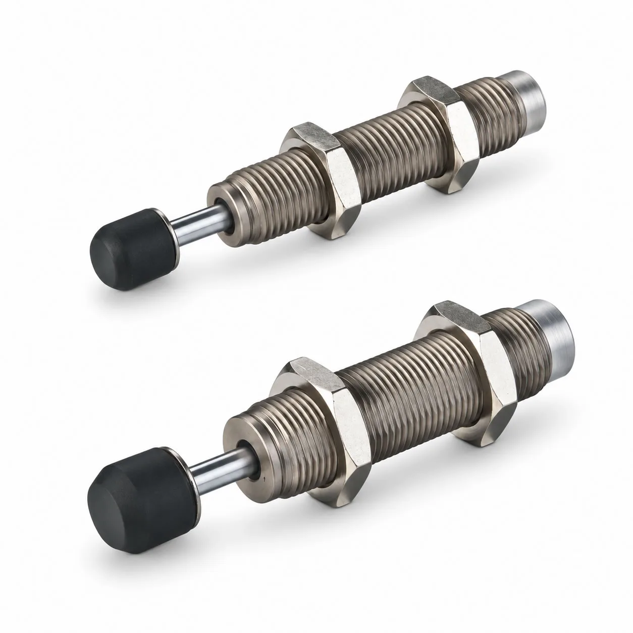
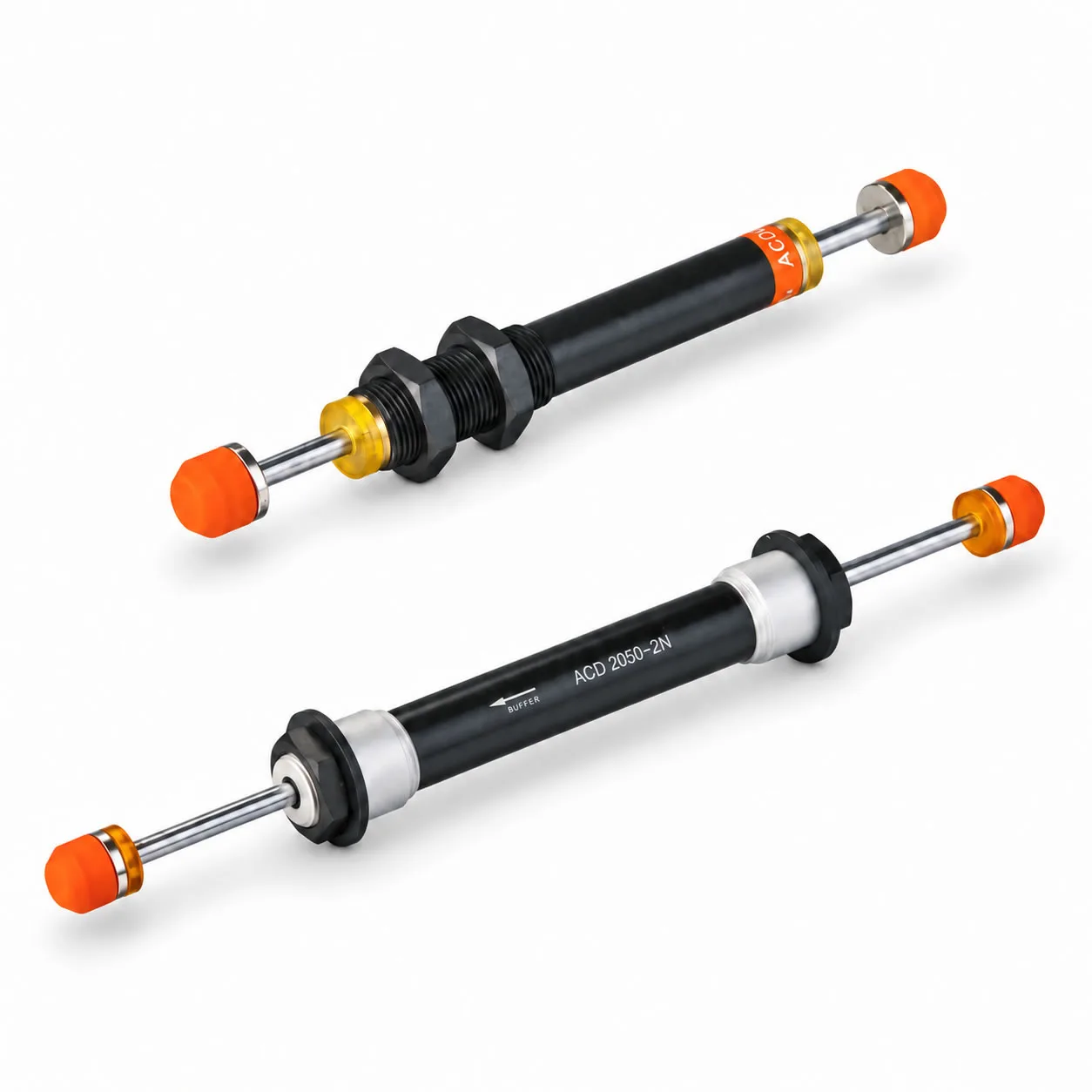
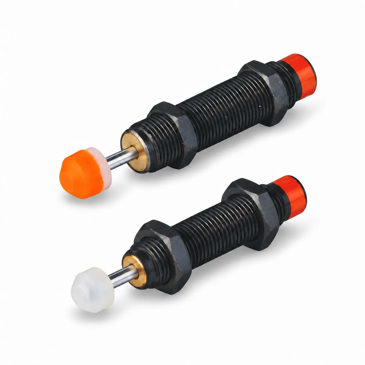
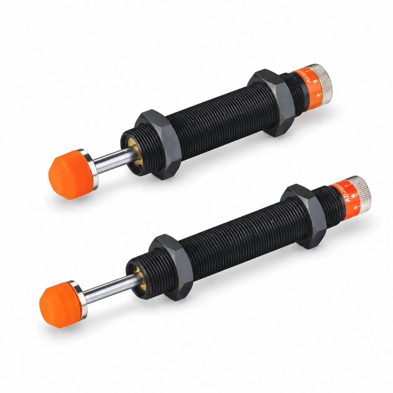
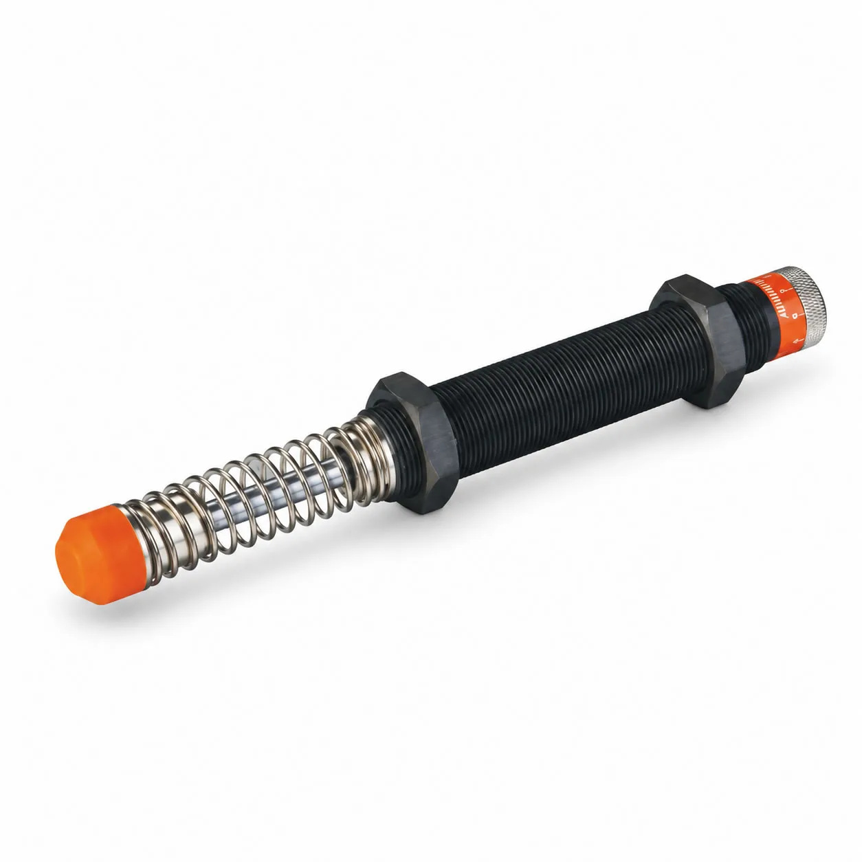
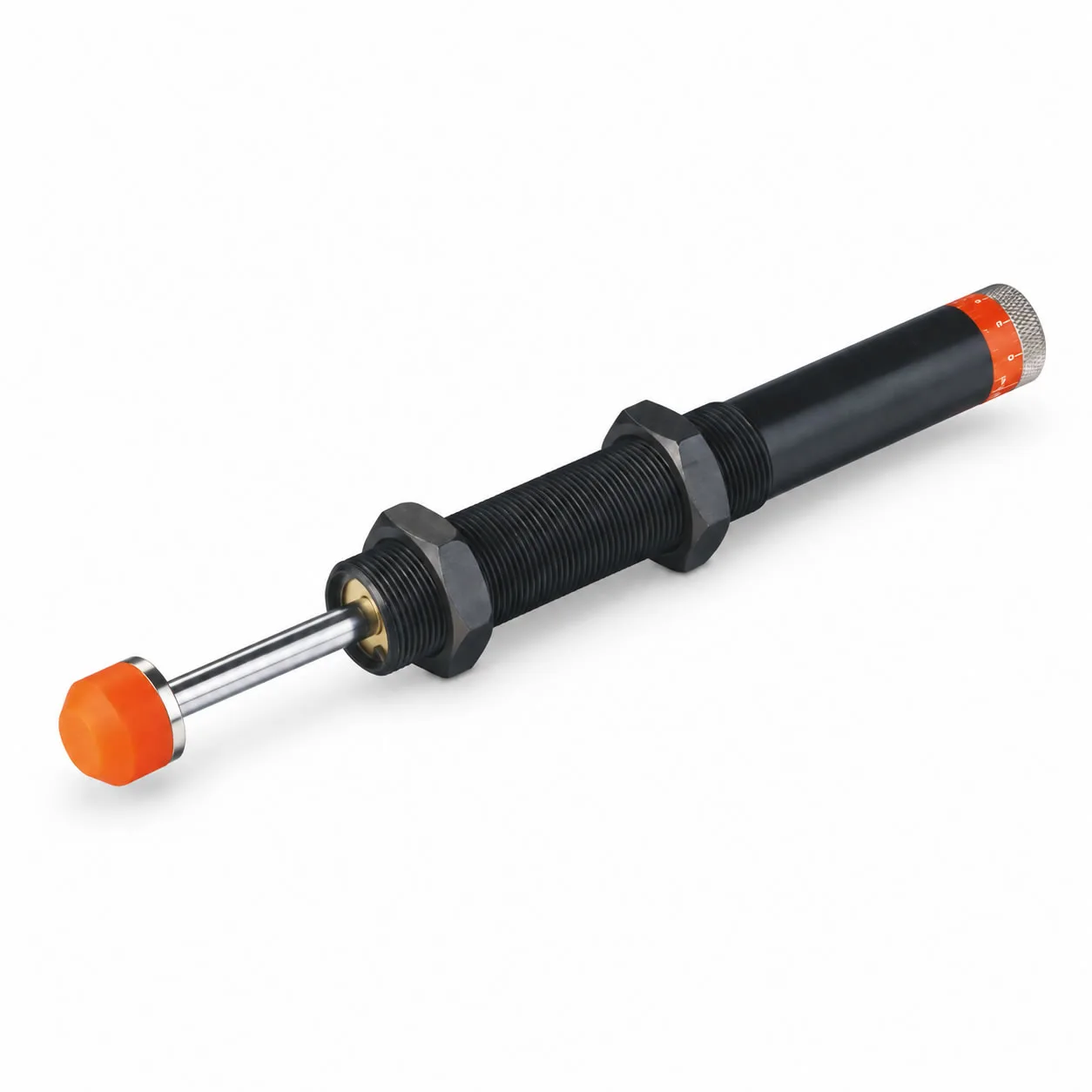
The HOMIPNEU AD series provides adjustable hydraulic damping for controlled deceleration of moving machine components. Models range from compact threaded units to larger shock absorbers for higher impact energy requirements.
| Parameter | Specification |
|---|---|
| Product Name | AD Series Adjustable Hydraulic Shock Absorber |
| Brand | HOMIPNEU |
| Damping Type | Manually adjustable hydraulic damping |
| Adjustment Scale | 0–8 |
| Adjustment Direction | Clockwise or counterclockwise, as described in the adjustment instructions |
| Stroke Range | 10–150 mm, depending on model |
| Maximum Energy per Cycle | 20–5,540 J, depending on model |
| Maximum Energy per Hour | 25,000–244,000 J/h, depending on model |
| Metric Mounting Threads | M14 × 1.5, M20 × 1.5, M25 × 1.5, M36 × 1.5, M42 × 1.5 |
| AD64 Series Mounting Thread | 2½″–12 UNF, as listed in the dimension table |
| Operating Temperature | −10°C to +80°C for models with a published temperature rating; confirm AD2550 and AD2580 separately |
| Cap Options | With-cap and without-cap versions for selected models |
| Without-Cap Identification | -N suffix on the models identified in the dimension tables |
Energy is expressed in joules: 1 J = 1 N·m. The effective mass and impact velocity limits must be checked together with energy per cycle and energy per hour; their maximum values should not be assumed to apply simultaneously.
Model Selection and Dimensions — AD14, AD20 and Selected AD25 Models
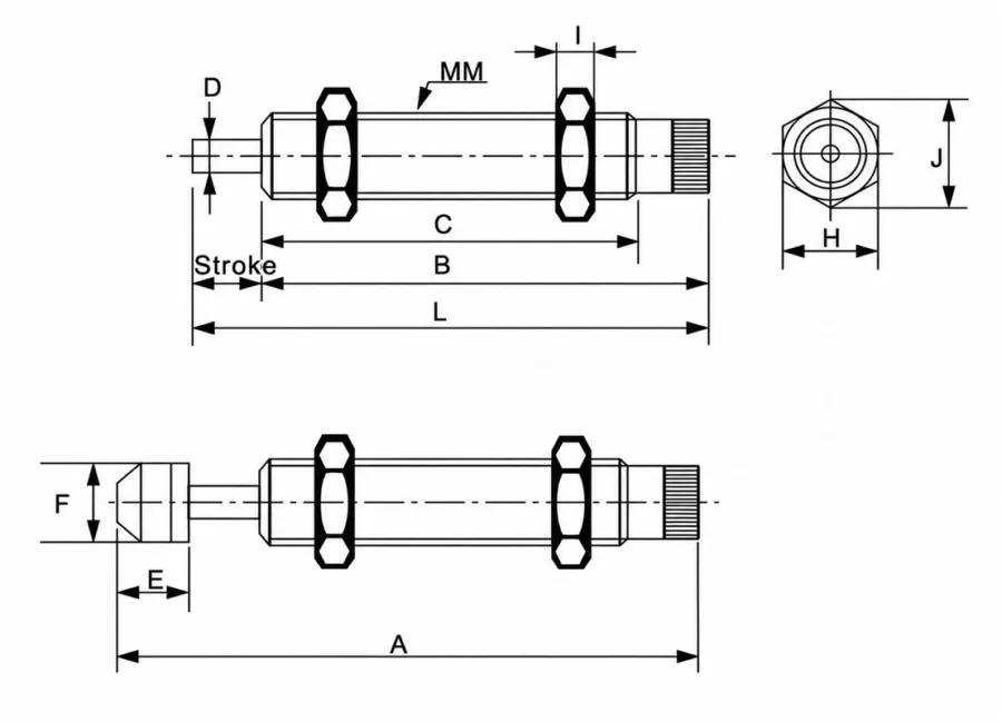
| Model Without Cap | Model With Cap | MM | L (mm) | B (mm) | C (mm) | D (mm) | A (mm) | E (mm) | F (mm) | H (mm) | I (mm) | J (mm) |
|---|---|---|---|---|---|---|---|---|---|---|---|---|
| AD1410-N | AD1410 | M14 × 1.5 | 89 | 79 | 65 | 4 | 101 | 15 | 12 | 19 | 6 | 21.6 |
| AD1412-N | AD1412 | M14 × 1.5 | 91 | 79 | 65 | 4 | 103 | 15 | 12 | 19 | 6 | 21.6 |
| AD1416-N | AD1416 | M14 × 1.5 | 104 | 88 | 72 | 4 | 116 | 15 | 12 | 19 | 6 | 21.6 |
| AD2016-N | AD2016 | M20 × 1.5 | 131 | 115 | 101 | 6 | 146 | 17 | 12 | 26 | 8 | 29.7 |
| AD2020-N | AD2020 | M20 × 1.5 | 135 | 115 | 101 | 6 | 150 | 17 | 12 | 26 | 8 | 29.7 |
| AD2025-N | AD2025 | M20 × 1.5 | 150 | 125 | 111 | 6 | 165 | 17 | 17.8 | 26 | 8 | 29.7 |
| AD2525-N | AD2525 | M25 × 1.5 | 143.5 | 118.5 | 101 | 8 | 164.2 | 20.7 | 22 | 32 | 10 | 36.7 |
| AD2530-N | AD2530 | M25 × 1.5 | 148.5 | 118.5 | 101 | 8 | 169.2 | 20.7 | 22 | 32 | 10 | 36.7 |
| Model | Stroke (mm) | Max. Energy Per Cycle (Nm) | Max. Energy Per Hour (Nm) | Max. Effective Weight (kg) | Max. Impact Speed (m/s) | Working Temperature (°C) |
|---|---|---|---|---|---|---|
| AD1410-N | 10 | 20 | 25000 | 80 | 3.0 | -10 to +80 |
| AD1410 | 10 | 20 | 25000 | 80 | 3.0 | -10 to +80 |
| AD1412-N | 12 | 20 | 26000 | 90 | 3.0 | -10 to +80 |
| AD1412 | 12 | 20 | 26000 | 90 | 3.0 | -10 to +80 |
| AD1416-N | 16 | 22 | 27000 | 120 | 3.0 | -10 to +80 |
| AD1416 | 16 | 22 | 27000 | 120 | 3.0 | -10 to +80 |
| AD2016-N | 16 | 25 | 28500 | 200 | 3.5 | -10 to +80 |
| AD2016 | 16 | 25 | 28500 | 200 | 3.5 | -10 to +80 |
| AD2020-N | 20 | 30 | 30000 | 250 | 3.5 | -10 to +80 |
| AD2020 | 20 | 30 | 30000 | 250 | 3.5 | -10 to +80 |
| AD2025-N | 25 | 35 | 30000 | 300 | 3.5 | -10 to +80 |
| AD2025 | 25 | 35 | 30000 | 300 | 3.5 | -10 to +80 |
| AD2525-N | 25 | 75 | 54000 | 400 | 3.5 | -10 to +80 |
| AD2525-2 | 25 | 75 | 54000 | 400 | 3.5 | -10 to +80 |
| AD2530-N | 30 | 86 | 60000 | 480 | 3.5 | -10 to +80 |
| AD2530 | 30 | 86 | 60000 | 480 | 3.5 | -10 to +80 |
Model Selection and Dimensions — AD2550 and AD2580
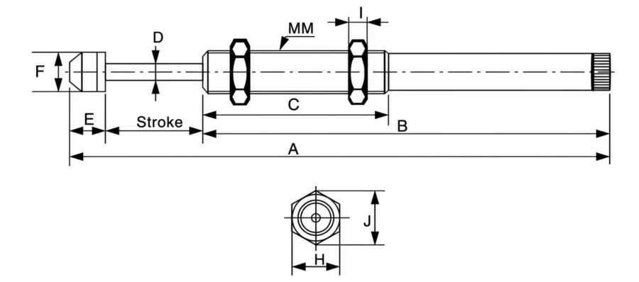
| Model | MM | A (mm) | B (mm) | C (mm) | D (mm) | E (mm) | F (mm) | H (mm) | I (mm) | J (mm) |
|---|---|---|---|---|---|---|---|---|---|---|
| AD2550 | M25 × 1.5 | 248.2 | 177.5 | 100 | 8 | 20.7 | 22 | 32 | 10 | 36.7 |
| AD2580 | M25 × 1.5 | 344.7 | 244 | 100 | 8 | 20.7 | 22 | 32 | 10 | 36.7 |
| Model | Stroke (mm) | Max. Energy Per Cycle (Nm) | Max. Energy Per Hour (Nm) | Effective Weight (kg) | Max. Impact Speed (m/s) |
|---|---|---|---|---|---|
| AD2550 | 50 | 98 | 90000 | 720 | 4.0 |
| AD2580 | 80 | 150 | 120000 | 800 | 4.0 |
Model Selection and Dimensions — AD2540, AD3625 and AD3650
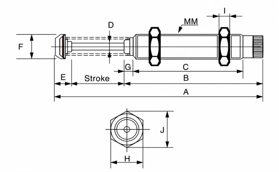
| Model | MM | A (mm) | B (mm) | C (mm) | D (mm) | E (mm) | F (mm) | G (mm) | H (mm) | I (mm) | J (mm) |
|---|---|---|---|---|---|---|---|---|---|---|---|
| AD2540 | M25 × 1.5 | 220.5 | 144.5 | 111 | 8 | 36.6 | 22 | 10 | 32 | 10 | 36.7 |
| AD3625 | M36 × 1.5 | 183.8 | 133 | 103 | 10 | 25.8 | 35 | 10 | 46 | 10 | 53 |
| AD3650 | M36 × 1.5 | 246.8 | 171 | 134 | 10 | 25.8 | 35 | 17 | 46 | 15 | 53 |
| Model | Stroke (mm) | Max. Energy Per Cycle (Nm) | Max. Energy Per Hour (Nm) | Max. Effective Weight (kg) | Max. Impact Speed (m/s) | Working Temperature (°C) |
|---|---|---|---|---|---|---|
| AD2540 | 40 | 100 | 85000 | 700 | 3.6 | -10 to +80 |
| AD3625 | 25 | 150 | 95000 | 1400 | 3.2 | -10 to +80 |
| AD3650 | 50 | 300 | 110000 | 1400 | 3.2 | -10 to +80 |
Model Selection and Dimensions — AD42 Models
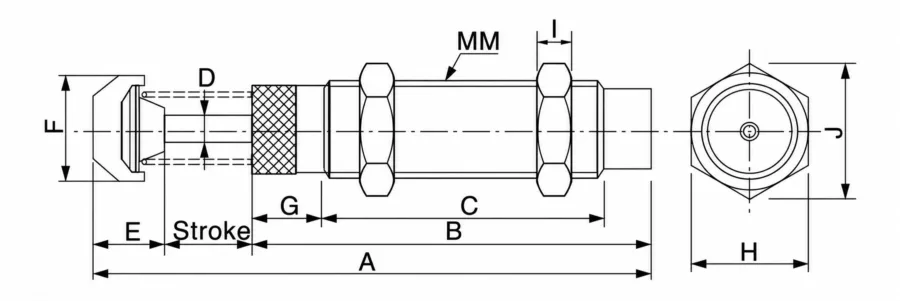
| Model | MM | A (mm) | B (mm) | C (mm) | D (mm) | E (mm) | F (mm) | G (mm) | H (mm) | I (mm) | J (mm) |
|---|---|---|---|---|---|---|---|---|---|---|---|
| AD4225 | M42 × 1.5 | 186.5 | 127.5 | 88 | 12 | 34 | 44.5 | 28.5 | 50 | 15 | 58 |
| AD4250 | M42 × 1.5 | 241 | 157 | 117.5 | 12 | 34 | 44.5 | 28.5 | 50 | 15 | 58 |
| AD4275 | M42 × 1.5 | 301.5 | 187.5 | 148 | 12 | 34 | 44.5 | 28.5 | 50 | 15 | 58 |
Model Selection and Dimensions — AD64 Models
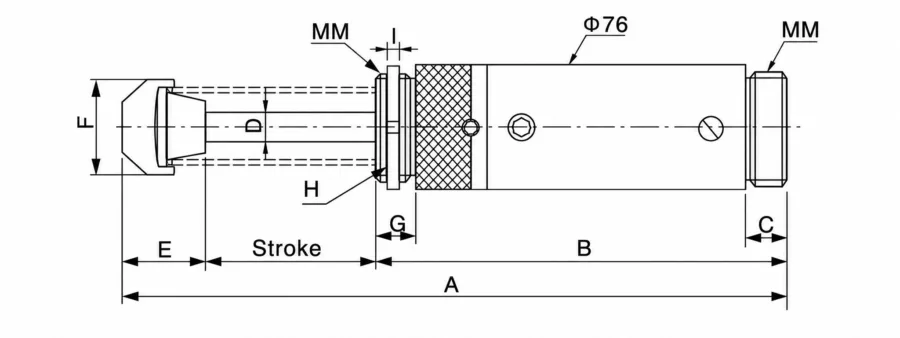
| Model | MM | A | B | C | D | E | F | G | H | I |
|---|---|---|---|---|---|---|---|---|---|---|
| AD64050 | UNF2 1/2–12 | 247.8 | 146 | 26 | 20 | 51.8 | 59 | 23 | Φ76.2 | 9.4 |
| AD64100 | UNF2 1/2–12 | 347.8 | 196 | 26 | 20 | 51.8 | 59 | 23 | Φ76.2 | 9.4 |
| AD64150 | UNF2 1/2–12 | 467.8 | 256 | 26 | 20 | 61.8 | 59 | 23 | Φ76.2 | 9.4 |
| Model | Stroke (mm) | Max. Energy Per Cycle (Nm) | Max. Energy Per Hour (Nm) | Effective Weight (kg) | Max. Impact Speed (m/s) | Working Temperature (°C) |
|---|---|---|---|---|---|---|
| AD4225 | 25 | 250 | 128000 | 2000 | 3.5 | −10 to +80 |
| AD4250 | 50 | 500 | 150000 | 4000 | 4.5 | −10 to +80 |
| AD4275 | 75 | 750 | 175000 | 6000 | 4.5 | −10 to +80 |
| AD64050 | 50 | 1850 | 185000 | 12500 | 4.0 | −10 to +80 |
| AD64100 | 100 | 3690 | 204000 | 18500 | 4.0 | −10 to +80 |
| AD64150 | 150 | 5540 | 244000 | 25000 | 4.0 | −10 to +80 |
All linear dimensions are in millimeters. Refer to the corresponding drawing for dimension references and confirm the complete model before ordering.
Product Features
Adjustable Hydraulic Damping
The damping setting can be adjusted to suit the application’s impact conditions. This allows the stopping response to be tuned during machine commissioning within the selected model’s operating limits.
Clearly Marked Adjustment Scale
The published adjustment instructions identify position 0 as the minimum setting and position 8 as the maximum setting. Adjustment changes the damping response; it does not increase the unit’s rated energy capacity.
Wide Range of Strokes and Capacities
Strokes from 10 to 150 mm and energy ratings up to 5,540 J per cycle provide options for compact automation mechanisms and larger industrial loads.
Piston Rod and Sealing Design
The piston rod and sealing arrangement are designed to limit oil leakage and support consistent hydraulic damping during repeated operation.
Wear- and Corrosion-Resistant Body Treatment
The outer body receives a surface treatment intended to improve resistance to wear and corrosion in industrial environments.
Threaded Body for Mounting
External threads support installation in suitable mounting brackets or threaded holes. The threaded surface also increases the exposed area available for heat dissipation.
Cap Options for Selected Models
Selected AD14, AD20 and AD25 models are listed with and without a cap, allowing the contact arrangement to be matched to the installation.
Applications
Automated Assembly Equipment
Helps cushion moving slides, transfer mechanisms and positioning fixtures as they approach a defined stopping point.
Provides adjustable impact control for reciprocating handling and transfer mechanisms. Selection must account for the number of impacts per hour.
Material Handling Systems
Suitable for evaluating controlled stopping of moving carriers, workpiece transfer devices and industrial handling assemblies.
Pneumatic Cylinder Mechanisms
Provides external hydraulic buffering where the machine requires additional impact absorption. Include cylinder thrust acting during the stopping stroke when calculating the load.
Machine Tool Automation
Can be integrated into loading, unloading and auxiliary positioning mechanisms requiring controlled deceleration.
Higher-Energy Industrial Mechanisms
The larger AD42 and AD64 models offer higher published energy capacities for applications that exceed the ratings of compact shock absorbers.
Why Choose HOMIPNEU
Models for Different Machine Sizes
The AD range covers multiple strokes, thread sizes and energy capacities, helping machinery builders compare suitable options within one product series.
Application-Based Selection
Provide the moving mass, impact velocity, driving force, cycle rate and available stopping distance so the proposed model can be checked against the operating conditions.
Detailed Installation Information
Model-specific drawings and dimension tables help engineers review mounting space, thread requirements and contact clearances before ordering.
Related Automation Components
HOMIPNEU also supplies pneumatic cylinders, solenoid valves, fittings and tubing for buyers sourcing components for complete automation assemblies.
FAQ
What is an adjustable hydraulic shock absorber?
An adjustable hydraulic shock absorber uses hydraulic resistance to absorb impact energy and decelerate a moving load. Its damping setting can be changed to suit the application within the model’s rated operating range.
How is the AD series different from the AC series?
The AD series provides manual damping adjustment. The AC series uses self-compensating damping within a specified range of operating conditions. Select the type according to the required stopping response and application conditions.
How do I adjust the damping?
The published instructions describe a rotary adjustment scale from 0 to 8, with 0 as the minimum setting and 8 as the maximum setting. Follow the instructions supplied with the exact model and check the stopping response during commissioning.
Does a higher adjustment setting increase the energy rating?
No. Adjustment changes the damping response. Energy per cycle, energy per hour, effective mass and impact velocity must remain within the selected model’s published limits.
How do I select the correct AD model?
Check the total energy per impact, impacts per hour, effective mass, impact velocity, required stroke and installation dimensions. Include any driving force that continues to act during deceleration.
Can the maximum mass operate at the maximum listed speed?
Not necessarily. The resulting energy must also stay within the allowable per-cycle capacity. Maximum mass and maximum speed are separate limits rather than a guaranteed operating combination.
What does the -N suffix mean?
For models identified in the cap-option dimension table, -N indicates the version without a cap. Confirm the complete model designation and matching drawing before ordering.
Does the AD shock absorber require compressed air?
No compressed air supply is required for its hydraulic damping function. It can be installed alongside pneumatically driven machinery.
Why must hourly energy absorption be checked?
Repeated impacts generate heat. A unit may remain below its per-cycle energy limit while exceeding its allowable hourly energy load at a high cycle rate.
OEM & ODM Support
HOMIPNEU accepts OEM & ODM inquiries for AD series adjustable hydraulic shock absorbers, including product identification, packaging and application-specific configuration requirements.
Please provide the required model or installation drawing, moving mass, impact velocity, driving force, operating frequency, temperature conditions and expected order quantity. Customization requests are subject to technical review and confirmation.