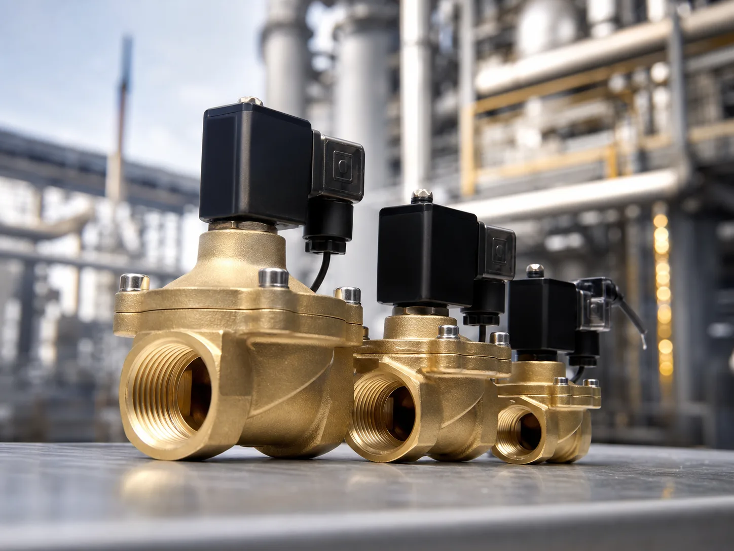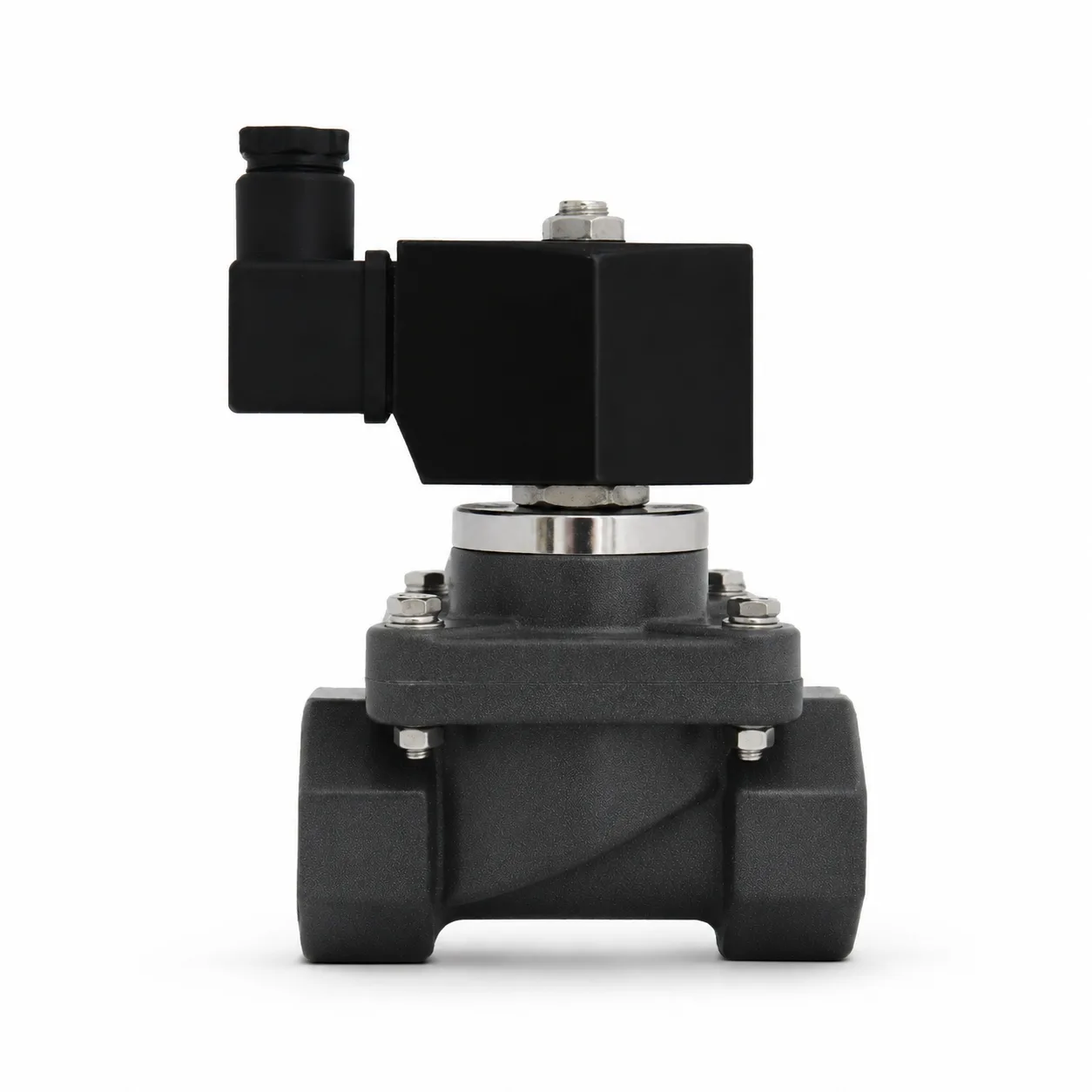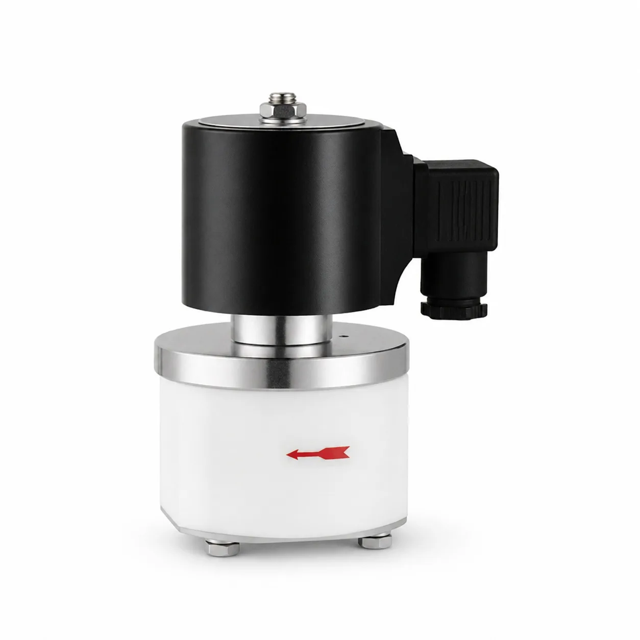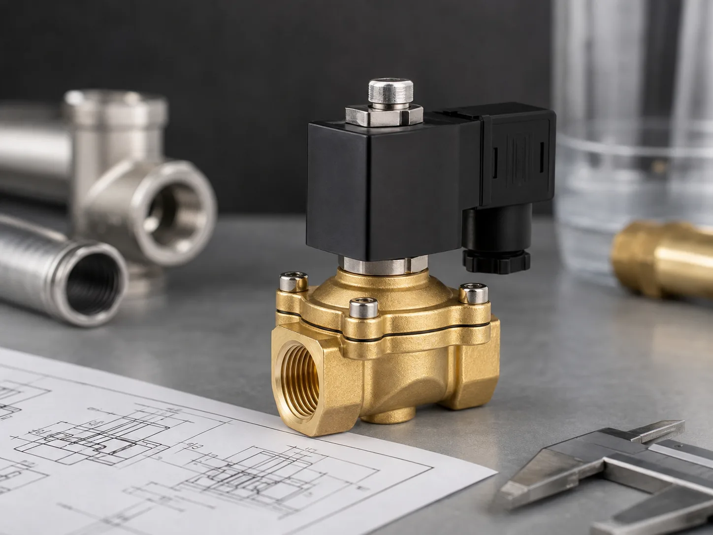
Selecting a PU220 brass solenoid valve begins with the fluid and operating conditions, not the pipe thread alone. Two PU220 models can share a similar appearance while offering very different orifice sizes and Cv values. A valve that fits the pipe may still restrict flow, use the wrong seal, receive the wrong coil voltage, or operate outside its pressure range. A clear selection process prevents those errors before equipment is built or a replacement valve is ordered.
The PU220 Series 2/2 Way Brass Solenoid Valve is a normally closed valve for electrical on/off control of air, water, compatible light oil, and other compatible neutral fluids. The range covers G1/8 through G1 ports, Cv values from 0.10 to 11.00, working pressure from 0.5 to 7 kgf/cm2, and an operating fluid temperature range of -5 to 80 degrees C. Available seal and voltage choices allow the valve to be configured for different machines, but every option must be confirmed against the real application.
1. Confirm the Required Valve Function
PU220 is a 2-port, 2-position normally closed fluid control valve. With the coil de-energized, the valve blocks the flow path. When the coil receives the specified voltage, the valve opens. This function suits supply, filling, washing, cooling, irrigation, air, and utility lines that should stop automatically when electrical power is removed.
It is not a directional valve for controlling both sides of a double-acting pneumatic cylinder. Cylinder direction normally requires a 5/2 or 5/3 valve, while a single-acting cylinder commonly uses a 3/2 valve. Use PU220 when the requirement is simple on/off control through one inlet and one outlet.
2. Identify the Working Medium First
The series is specified for air, water, and compatible oil, but that description does not make every fluid acceptable. Record the exact medium, concentration, additives, contamination, temperature, and viscosity. For oil service, the published viscosity limit is 50 cSt. A thicker oil may cause slow movement, incomplete opening, or unreliable closing.
Brass is practical for many neutral water, air, and general utility applications. It should not be assumed suitable for seawater, concentrated brine, aggressive chemicals, food-contact service, oxygen, fuel gas, or corrosive process fluids. Those duties may require stainless steel, engineering plastic, dedicated approvals, or a different internal design. For steam, select a valve specifically rated for steam instead of applying the PU220 temperature figure without further review. The article Water, Steam and Air Solenoid Valves: Key Differences explains why media categories are not interchangeable.
3. Check Pressure at Every Operating State
PU220 has a published working pressure range of 0.5 to 7 kgf/cm2 and maximum pressure resistance of 10.5 kgf/cm2. Maximum pressure resistance is not the normal operating limit. The selection must use the working range and include normal inlet pressure, maximum inlet pressure, downstream pressure, pressure during startup, and pressure when pumps or compressors stop.
The 0.5 kgf/cm2 lower limit is also important. Do not assume the valve will operate reliably at zero pressure simply because it is described as a direct-drive type. Gravity tanks, drained lines, and low-head systems may fall below the minimum. Test the selected model at the lowest real pressure if the application operates near that boundary.
4. Select by Port, Orifice, and Cv
Port size determines pipeline connection, but the orifice and Cv value determine how freely the medium can pass. The PU220-03AR and PU220-03A both use a G3/8 connection, yet the first has an 8 mm orifice and Cv 1.00 while the second has a 13 mm orifice and Cv 4.00. Treating them as equivalent because the thread matches can create a major sizing error.
| Model | Port | Orifice | Cv | Typical Selection Direction |
|---|---|---|---|---|
| PU220-01AR | G1/8 | 1.5 mm | 0.10 | Small dosing, pilot, laboratory, or compact utility lines |
| PU220-02AR | G1/4 | 2.3 mm | 0.18 | Low-flow water, air, and equipment circuits |
| PU220-03AR | G3/8 | 8 mm | 1.00 | Moderate flow where a compact body is preferred |
| PU220-03A | G3/8 | 13 mm | 4.00 | Higher flow through a G3/8 connection |
| PU220-04A | G1/2 | 13 mm | 4.00 | General medium-flow water or air lines |
| PU220-06A | G3/4 | 20 mm | 8.60 | Larger equipment and utility pipelines |
| PU220-08A | G1 | 25 mm | 11.00 | Highest flow option in the PU220 range |
Calculate or estimate the required flow at the actual pressure difference and medium. An oversized valve increases body size and cost and may worsen hydraulic shock. An undersized valve creates pressure loss and longer filling or cooling time. If the flow requirement is critical, provide flow rate, inlet pressure, outlet pressure, and fluid properties to the supplier instead of selecting from pipe size alone.
5. Match the Seal to the Fluid
PU220 can be supplied with NBR, VITON, or EPDM seals. NBR is widely used for compressed air, water, and many petroleum-based oils under suitable conditions. EPDM is often considered for water and certain compatible polar fluids, but it is generally not chosen for petroleum oil. VITON is useful for many oils, fuels, higher temperatures, and chemical exposures, but it is not universally compatible with every medium.
These are general material directions, not a final compatibility approval. Confirm the exact fluid name, concentration, additives, temperature, cleaning chemicals, and expected exposure time. The coil, diaphragm, seat, and other wetted components must also be compatible; selecting the seal alone does not approve the entire valve for an unfamiliar fluid.
6. Choose the Correct Coil Voltage
Common PU220 voltage options include DC12V, DC24V, AC24V, AC110V, and AC220V. The coil marking must match the control output and local electrical design. DC24V is common in automation panels, while AC voltages are often found in standalone equipment and utility systems. Never order a voltage from memory when replacing an existing valve; read the nameplate and verify the supply with the electrical documentation.
Also check frequency for AC coils, connector style, cable entry, duty cycle, and enclosure protection. A continuously energized coil generates heat. High ambient temperature, direct sun, poor panel ventilation, and nearby hot equipment can reduce operating margin even when the fluid remains below 80 degrees C. Fluid temperature and ambient temperature are separate selection inputs.
7. Review Installation and Pipeline Effects
Install the valve in the marked flow direction. Reverse installation can prevent correct sealing or opening. Provide adequate space for coil removal, electrical connection, and future service. Support the pipe so that its weight and misalignment do not load the valve body. Flush new piping before installation because metal chips, sealant, scale, and dirt can lodge on the seat.
For water lines, consider water hammer. A fast-closing valve in a long pipeline can generate a pressure surge above the normal gauge reading. Reduce liquid velocity, review pipe length, add suitable surge control, or choose a valve and system arrangement designed for the transient. Do not use the 10.5 kgf/cm2 pressure-resistance figure as permission to ignore surge analysis.
8. Match the Model to the Application
Small PU220-01AR and PU220-02AR models suit compact equipment, controlled dosing, laboratory utilities, or low-flow air and water lines. The PU220-03AR provides a larger 8 mm path while retaining a G3/8 connection. PU220-03A and PU220-04A share a 13 mm orifice and Cv 4.00 for higher-flow equipment circuits.
PU220-06A and PU220-08A serve larger G3/4 and G1 pipelines in cleaning equipment, filling systems, irrigation, water treatment auxiliaries, HVAC support circuits, and general industrial utilities. A larger model should still be checked against cycle time, pressure difference, coil duty, water hammer, and available installation space.
Common Selection Mistakes
- Choosing only by the thread printed on the pipe.
- Ignoring the large Cv difference between PU220-03AR and PU220-03A.
- Assuming the valve operates from zero pressure when the published minimum is 0.5 kgf/cm2.
- Using maximum pressure resistance as the normal working pressure.
- Selecting a seal without identifying additives or cleaning chemicals.
- Using PU220 for steam, seawater, strong chemicals, or hazardous gas without written compatibility and approval confirmation.
- Confusing a 2/2 on/off valve with a cylinder directional valve.
- Ignoring AC frequency, connector, cable protection, ambient heat, or continuous coil energization.
- Installing against the flow arrow or failing to flush the pipeline.
Information to Include in a PU220 RFQ
- Exact medium and concentration
- Normal and maximum fluid temperature
- Normal, minimum, and maximum inlet pressure
- Outlet pressure or pressure differential
- Required flow rate and acceptable pressure drop
- Pipe thread and preferred PU220 model
- Fluid viscosity for oil service
- Required seal material
- Coil voltage, AC frequency, connector, and duty cycle
- Ambient temperature and indoor or outdoor location
- Cycle frequency and fail-closed requirement
- Quantity, labeling, packaging, and spare coil needs
FAQ
Can PU220 control both air and water?
Yes, when the chosen body, seal, pressure, temperature, and connection are compatible with the actual air or water system. The same ordered configuration should not automatically be moved between different media without checking those conditions.
Which PU220 model has a G1/2 port?
PU220-04A uses a G1/2 port with a 13 mm orifice and Cv 4.00. Confirm the required flow and pressure drop rather than selecting it only because the pipeline is G1/2.
Can PU220 work at zero pressure?
The published working range starts at 0.5 kgf/cm2. Applications near zero pressure should not assume reliable operation; provide the minimum inlet and outlet conditions for confirmation or select a valve specifically intended for zero-pressure service.
Is PU220 suitable for steam?
PU220 is described for air, water, compatible oil, and neutral fluids within its rated range. Steam should use a dedicated steam-rated valve whose body, seals, coil, and pressure-temperature limits are confirmed for the service.
Final Selection Approach
A reliable PU220 selection follows a fixed order: function, medium, pressure, flow, port, orifice, seal, voltage, temperature, and installation environment. The model table narrows the range, but the final decision comes from actual operating data. Buyers can review the complete solenoid valve category when the application needs a different body material, a steam-rated design, a compact zero-pressure valve, or directional control rather than simple on/off flow.